


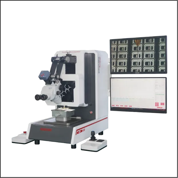
A push-pull testing machine can pull, shear and push, but that flexibility is exactly where trouble starts. The three modes do not measure the same physical quantity, so substituting one for another does not simply change the number — it changes what the number means. We have watched a supplier clear an incoming inspection with a pull result and then fail the same part against a shear specification, not because the bond was good or bad, but because the two tests were asking different questions about the same joint.
This guide follows the order we use when a customer's test plan has to be mapped onto a bench. We will cover five things in sequence: the physical quantity each mode captures, when pull is the right choice, when shear is, when push and downforce are, and what a substituted mode actually costs you. Then we will look at how a bench is configured so the modes stay separate in daily use.
The short version, if you only read this far
- Pull loads the joint along its axis, shear loads the interface in its own plane, push displaces a seated feature.
- A pull result is a chain of links, so the peak force is meaningless without a failure location code.
- Shear is the most direct probe of whether the interface itself formed.
- Substituting one mode for another hides the interface you were supposed to qualify.
Step 1: Separate the Three Physical Quantities Before You Pick Up a Tool
Each mode loads the specimen in a different direction, and each direction mobilises a different failure path. Write the three down before you choose anything, because the choice of tool, speed and acceptance limit all follow from this one table.
| Mode | Direction of the load | What the peak force describes | Failure path it exposes |
|---|---|---|---|
| Pull, bond wire pull (WP) | Along the axis of the interconnect | The force at which the interconnect separates | The weakest link anywhere along the wire, lead or joint |
| Shear, solder joint push (BS) and die shear (DS) | Sideways, inside the plane of the bond | The strength of the interface itself | The bond line and the material immediately above it |
| Push and downforce, downforce (DP) and pullout (TP) | Vertically down, or out along the seating direction | The force needed to displace a seated feature | Retention: solder joint, crimp, or contact feature |
Three directions, three failure paths, three different engineering messages. A bench that can move in all three directions is still running three separate measurements, so treat it as three tests that happen to share a frame. With that separation clear, the next question is which of the three your own test plan is really asking for, and pull is the one people reach for first.
Step 2: Use Pull When the Question Is Whether the Whole Interconnect Holds
Reach for pull when you want to know whether the complete interconnection survives a mechanical load. Bond wire pull, coded WP, is the classic example: a fine hook slips under the wire loop and lifts, and the recorded peak is the force at which something gives way. That something is the point.
A pull result is a series, not a single link. The load path runs from the hook into the loop, through the first bond, back through the loop, and out through the second bond. The break can happen at any of those places, and two very different weaknesses can produce a similar peak force. This is why every credible pull procedure pairs a force value with a failure location code rather than a number on its own.
- Use pull for wire bonds, inner leads, ribbon and lead frame connections, and any interconnect you can lift along its own axis.
- Check that the hook sits symmetrically under the loop and pulls perpendicular to the bond surface. An angled hook adds a shear component and moves the failure.
- Classify the break location for every specimen. A mixed set of force values from mixed failure modes cannot be averaged into anything useful.
- Inspect the hook the same way you would inspect a tensile grip, because small tooling makes small alignment errors matter a great deal.
Pull work lives naturally on a bench built around fine tooling and light, controlled motion, which is the family described on our wire bond strength tester page. Pull answers the question the customer usually asks first, but it is a poor probe of the interface itself, and that is where shear takes over.
Step 3: Use Shear When the Question Is Whether the Interface Actually Formed
Choose shear when the interface is the thing you have to qualify. A shear tool contacts the side of the component at a defined height and pushes laterally, so the measured strength comes mostly from the bond line rather than from the wire or lead above it. Solder joint push is coded BS and die shear is coded DS, and both appear constantly in package quality control.
Two details shape a shear result more than most people expect. The first is tool standoff height, the distance between the blade and the substrate. Set it too high and the tool rides up over the component; set it too low and the blade digs into the substrate, so the force reflects the tool instead of the joint. The second is the shear rate, because an interface can behave differently when it is loaded quickly than when it is loaded slowly. Both belong in the procedure and both belong in the record.
| Shear application | What it qualifies | Setup point that decides the result |
|---|---|---|
| Die shear (DS) | The die attach interface under a mounted chip | Blade height relative to the die face and the substrate |
| Solder joint push (BS) | The joint between a component and its pad | Contact point on the joint, and the shear rate |
| SMT component and BGA matrix push | A whole array of joints, one by one or in sequence | Indexing accuracy across the array, so each joint is approached the same way |
A shear value also reminds you that the test only reports on the interfaces the blade can reach. If a die is held by underfill or a heavy encapsulant, the shear path may be constrained by material that has nothing to do with the bond, and the number becomes an upper bound rather than a bond strength. When we configure a shear force push pull testing machine, we always ask what surrounds the joint, because the answer decides whether a clean interface measurement is even possible. Shear settles the interface question, but a different question entirely needs a tool that moves straight down.
Step 4: Use Push and Downforce When the Question Is Retention or Displacement
Switch to push when the engineering question is whether a feature stays where it was put. Downforce, coded DP, drives a tool vertically into a ball, a bump or a pin. Pullout, coded TP, does the opposite and pulls a feature out along its seating direction. The two together cover retention, insertion and extraction work that neither pull nor shear can reach.
- Gold ball push and bump push in package assembly, where the tool presses on the ball rather than lifting it.
- Pin push in and push out on connectors and headers, where the question is seating force rather than joint strength.
- Solder ball repeated push fatigue, where the same ball is loaded again and again to see how a joint degrades under cycling.
- Pullout of a seated terminal or lead, where you need to know the force that frees it rather than the force that breaks it.
Push mode is also where interpretation gets slippery. A high push force can mean a strong joint, or it can mean the tool was contacting the wrong surface and the reading was really a mechanical obstruction. A low reading can mean a weak joint, or a tool that slipped off the shoulder. That ambiguity is the reason push work benefits from a full load displacement curve rather than a lone peak value: the shape of the curve usually shows which of those things happened.
This is where a modular bench earns its keep. The WBE-9088B carries an automatic rotating module, available with one to six modules covering push, shear, tension, pullout and downforce either individually or in combination, and each sensor keeps its own anti collision and overload protection. In practice that means a recipe cannot be run with the previous tool still mounted, which is the single most common way a mode gets mixed up on a busy line. The six module configuration is described on our six module push pull testing machine page, and the same platform handles the broader package work covered by our semiconductor push pull tester. Once the modes are physically separated, the remaining risk is a decision made before the tool was ever mounted, which is where a substituted mode causes the most damage.
Step 5: Recognise What a Substituted Mode Costs You
Substituting one mode for another does not produce a wrong number. It produces a correct number for a question you were not asked, and that is worse, because it passes. We watched this happen at a packaging house that was qualifying a new wire bond process. The internal specification called for shear at the ball bond, but the line had only a pull setup available and decided to substitute it temporarily so the build would not slip.
The pull results passed comfortably, so the process was released. When the customer's own incoming shear test arrived a few weeks later, a portion of the parts failed. Nothing about the product had changed. The pull test had been loading a strong loop and a strong second bond, which hid a weak first bond interface that only shear would have exposed directly. The lesson is not that one mode is stricter. The lesson is that the two modes stress different interfaces, so passing one says almost nothing about the other.
Before you authorise any substitution, answer three questions in writing. Which interface must fail for this test to be informative? Does the substitute mode load that interface first, or does it load something stronger in series? And was the acceptance limit derived under the original mode? If the limit came from a shear study, applying it to a pull result is a category error even though the units look identical.
One habit removes most of this risk: keep the mode, the tool and the recipe together as a single unit. When each module carries its own tooling and its own stored procedure, an operator physically cannot run a shear recipe with a pull hook fitted. The platforms collected on our bond tester machine range are organised around that idea, and the way these benches are deployed in production is shown on our semiconductor application page. If you want the measurement side in more depth before you choose a mode, the practical guide to accurate force testing covers load cell choice, calibration and fixture effects.
Frequently Asked Questions About Modes on a Push-Pull Testing Machine
Can one bench really run all three modes?
Yes, provided each mode keeps its own tooling, recipe and calibration path. The frame is shared, but the measurement chain is not, so the modules have to be treated as separate setups. Treating them as interchangeable settings on one machine is what causes most mode errors in the first place.
Which mode is stricter?
Neither is stricter in the abstract, because they load different interfaces. A pull test can look generous while hiding a weak interface that shear would expose immediately. The useful question is which interface you are trying to qualify, and the document you answer to has usually already made that choice for you.
Why does test speed change the result?
Many bond interfaces and solders show a rate dependence, so a faster test can shift the measured force, and a fast rate also adds dynamic content to the signal. Because the method fixes a rate for a reason, deviating from it makes your data hard to compare with the reference set the limits were built on.
Do I still need failure location codes if I have the force value?
Yes. Force alone cannot tell you which interface failed, and two very different problems can produce a similar peak. Classifying the failure location is what turns a number into an engineering conclusion, and it is usually the first thing a customer's engineer or an auditor asks to see.
Pull, shear and push are not three settings on one push-pull testing machine. They are three measurements that answer three different questions about the same joint, and the standard you work to has already decided which of those you are supposed to prove. Match the mode to the interface, keep the tooling and the rate with the recipe, and the bench becomes a reliable witness for your process instead of a source of arguments between you and your customer.
One frame, three modes, no mixed tooling
Review module configurations where push, shear, tension, pullout and downforce each keep their own sensor protection, so every recipe on a push-pull testing machine carries the tool it belongs to.
Compare push pull module setups Send your test plan and bond list